IGEM/UP/1B Edition 3 +A: 2012 - Tightness testing and direct purging of small Liquefied Petroleum Gas/Air, NG and LPG installations
The IGEM/UP/1B standard covers tightness testing and direct purging of pipework containing either LPG/Air, natural gas or LPG and applies to any section of pipework, including meters, having the following:
- MOP at the outlet of the emergency control valve not exceeding 2 bar for NG and LPG/Air and
- A nominal bore of not greater than 35 mm and
- A maximum badged capacity through the primary meter of not exceeding 16 m3 h-1 and
- A maximum installation volume supplying an individual dwelling or non domestic premises of 0.035 m3 and
- LPG/Air Installations – OP at the outlet of the primary meter and any point in the section to be tested not exceeding 21 mbar or
- NG Installations – OP at the outlet of the primary meter and any point in the section to be tested not exceeding 21 mbar or
- LPG Installations – OP at the outlet of the final stage regulator and any point in the section to be tested not exceeding 37 mbar.
They apply to tightness testing in the following circumstances:
- New pipework
- Alteration to, replacement of, reuse of, or upgrading existing pipework
- New extensions to existing pipework
- Prior to any work on existing pipework
- Where there is a known or suspected gas leak in the pipework
- Where there has been a complete loss of pressure for any reason
- Routine testing of existing pipework
- Immediately before purging pipework (except when taking pipework permanently out of service).
And to direct purging in the following circumstances:
- New pipework
- Alteration to, replacement of or reuse of, existing pipework
- New extensions to existing pipework
- Where there has been a complete loss of pressure for any reason
- Where there is the possibility of air being present in the pipework
- Where pipework is to be taken out of service temporarily or permanently.
Introduction
1.1 These Procedures supersede IGE/UP/1B Edition 1, Communication 1675, which is obsolete.
1.2 These Procedures have been drafted by a Panel appointed by the Institution of Gas Engineers and Managers’ (IGEM’s) Gas Utilization Committee, subsequently approved by that Committee and published by the authority of the Council of the Institution.
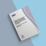
1.3 IGE/UP/1 Edition 2 deals with all aspects of strength and tightness testing and direct purging of selected 1st, 2nd and 3rd family gases within its wide scope and at a maximum operating pressure (MOP) not exceeding 16 bar.
IGE/UP/1A Edition 2 deals with the special case of strength and tightness testing and direct purging of volumes not exceeding 1 m3 and operating pressure (OP) not exceeding 40 mbar and using Natural Gas (NG).
IGE/UP/1B Edition 2 deals with all aspects of tightness testing and direct purging of small NG installations with a meter of capacity not exceeding U16 and supply MOP (MOPu) not exceeding 2 bar. It has been published to take into account the extended scope of BS 6891 and the introduction of BS 6400-2.
For tightness testing of small liquefied petroleum gas (LPG) installations, BS 5482-1 or 3 or BS EN ISO 10239 apply, as appropriate. For greater volume, IGE/UP/1 Edition 2 applies.
Figure 1 will assist in selecting the appropriate standard.
Note: “MOP”, “OP” and other new terms have been introduced to reflect gas pressure terminology used in European standards. Appendix 1 defines these terms and it is possible to equate them to terms used in Edition 1. These terms will arise in all relevant IGEM technical publications in future and, possibly, in other standards.
For a new system of installation pipework, the onus is on the designer to establish both the maximum incidental pressure (MIP) and MOP. For an existing system of installation pipework, the onus is on the designer/owner of the system to ensure that any increase in pressure within the system will not result in OP exceeding MOP of the system and on the gas transporter/meter asset manager (GT/MAM) to ensure that any change in their pressure regimes due to fault conditions will not jeopardise the safety of the downstream system. This involves effective communication between the GTs/MAMs and system designers/owners.
1.5 These procedures make use of the terms “should”, “shall” and “must” when prescribing particular procedures. Notwithstanding Sub-Section 1.8:
a) The term “must” identifies a requirement by law in Great Britain at the time of publication.
b) The term “shall” prescribes a procedure that, it is intended, will be complied with in full and without deviation.
c) The term “should” prescribes a procedure that, it is intended, will be complied with unless, after prior consideration, deviation is considered to be acceptable.
Such terms may have different meanings when used in legislation, or HSE ACoPs or guidance, and reference needs to be made to such statutory legislation or official guidance for information on legal obligations.
1.6 The primary responsibility for compliance with legal duties rests with the employer. The fact that certain employees, for example “responsible engineers”, are allowed to exercise their professional judgement does not allow employers to abrogate their professional responsibilities. Employers must:
- have done everything to ensure, so far as is reasonably practicable, that there are no better protective measures that can be taken other than relying on exercise of professional judgement by “responsible engineers”
- have done everything to ensure, so far as is reasonably practicable, that “responsible engineers” have the skills, training, experience and personal qualities necessary for the proper exercise of professional judgement • have systems and procedures in place to ensure that the exercise of professional judgement by “responsible engineers” is subject to appropriate monitoring and review
- not require “responsible engineers” to undertake tasks which would necessitate the exercise of professional judgement that is beyond their competence. There should be written procedures defining the extent to which “responsible engineers” can exercise their professional judgement. When “responsible engineers” are asked to undertake tasks that deviate from this, they should refer the matter for higher review.
1.7 It is widely accepted that the majority of accidents at work generally are in some measure attributable to human as well as technical factors in the sense that actions by people initiated or contributed to the accidents, or people might have acted better to avert them.
It is therefore necessary to give proper consideration to the management of these human factors and the control of risk. To assist in this, it is recommended that due cognisance be taken of HS(G)48.
1.8 Notwithstanding Sub-Section 1.5, these Procedures do not attempt to make the use of any method or specification obligatory against the judgement of the responsible engineer. Where new and better techniques are developed and proved, they should be adopted without waiting for modification to these Procedures. Amendments to these Procedures will be issued when necessary, and their publication will be announced in the Journal of the Institution and other publications as appropriate.
1.9 Requests for interpretation of these Procedures in relation to matters within their scope, but not precisely covered by the current text, should be addressed in writing to Technical Services, IGEM, Charnwood Wing, Holywell Park, Ashby Road, Loughborough, Leicestershire, LE11 3GH and will be submitted to the relevant Committee for consideration and advice, but in the context that the final responsibility is that of the engineer concerned. If any advice is given by or on behalf of IGEM, this does not relieve the responsible engineer of any of his or her obligations.
1.10 These Utilization Procedures were published on 24th March 2006.
They may be used rather than the procedures given in IGE/UP/1B Edition 1 immediately but a lead-in period is allowed permitting the use of Edition 1 until 24th June 2006.
1.11 The Amendments issued in October 2008 are incorporated within this electronic version.
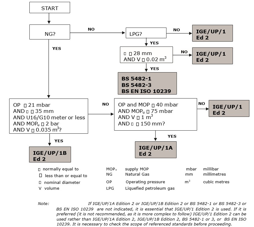
FIGURE 1 - ALGORITHM TO SELECT TESTING AND PURGING STANDARDS
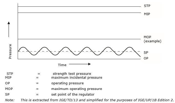
FIGURE 2 - RELATIVE PRESSURE LEVELS
Scope
2.1 This Standard applies to LPG/Air, NG, and LPG installations as illustrated in
Figure 3.
2.2 This Standard applies to any section of installation pipework, including meters, having the following:
- MOP at the outlet of the emergency control valve (ECV) not exceeding 2 bar for NG and LPG/Air and
- a nominal bore of not greater than 35 mm (DN32, R1¼) and
- a maximum badged capacity through the primary meter of not exceeding 16 m3 h-1 and
- a maximum installation volume (IV) supplying an individual dwelling or non domestic premises of 0.035 m3 and
- LPG/Air Installations - OP at the outlet of the primary meter and any point in the section to be tested not exceeding 21 mbar or
- NG Installations - OP at the outlet of the primary meter and any point in the section to be tested not exceeding 21 mbar or
- LPG Installations - OP at the outlet of the final stage regulator and any point in the section to be tested not exceeding 37 mbar.
Note 1: There are some existing NG installations, where MOPu exceeds 75 mbar that have been installed without the facility of a meter inlet valve (MIV). These installations are not within the scope of IGEM/UP/1B but advice on testing and purging is given in Appendix 4.
Note 2: Installations of larger volume are rare in domestic premises. However, if there is any doubt, it is advisable to calculate IV in accordance with Appendix 7 before using this Standard.
Note 3: LPG service pipework is not within scope of this Standard and is covered by UKLPG Code of Practice 22.
Note 4: Propane and Butane installations typically operate at 37 mbar and 28 mbar.
Note 5: The scope of this Standard limits the IV to 0.035 m3. For example, the following installations have a volume less than 0.035 m3:
- 25 m of 35 mm copper pipework (assuming U6 fitted)
- 10 m of 35 mm copper pipework (assuming U16 fitted)
- 20 m of 32 mm corrugated stainless steel tube (CSST) pipework (assuming U6 fitted) • 8 m of 32 mm CSST pipework (assuming U16 fitted).
2.3 This Standard covers tightness testing and direct purging of pipework containing either LPG/Air, NG, or LPG.
Note 1: There are Standards for other installation locations which are not individual dwellings – PD 5482-3, or BS EN ISO 10239 or IGE/UP/1 apply, as appropriate (see Figure 1).
Note 2: Historically, BS 6891 (which preceded IGE/UP/1B Edition 1 for “soundness testing”) and IGE/UP/1B Edition 1 and 2 have not required strength testing. This philosophy continues for IGEM/UP/1B Edition 3 (for components of MOP 75 mbar) as there is no significant case evidence for introducing strength testing, the risk associated with failure of integrity is comparatively low (due to low energy contained) and the available materials and methods of construction are such as to give confidence that integrity will be assured. Steps are given in the tightness test section to check that jointing has been correctly carried out.
2.4 This Standard applies to tightness testing in the following circumstances:
- new installations
- alteration to, replacement of, or re-use of, existing installations
- new extensions to existing pipework
- prior to any work on existing installations
- where there is a known or suspected gas escape
- where there has been a complete loss of supply pressure i.e. upstream of the ECV, or of installation pressure
- routine testing of existing installations
- immediately before purging of installations (except when taking components permanently out of service).
Note: This Standard may not need to be applied when carrying out routine maintenance, such as servicing.
2.5 This Standard applies to direct purging in the following circumstances: • new installations
- alteration to, replacement of, or re-use of, existing installations
- new extensions to existing installations
- where there has been a complete loss of installation pressure • where there is the possibility of air being present in an installation.
Note 1: This Standard may not need to be applied when carrying out routine maintenance, such as servicing.
Note 2: This Standard refers throughout to purging when there is the possibility air may be present in the gas installation. The principles may be used when there could be other gases in the installation other than the gas with which the installation is currently supplied, for example when an installation is converted from one fuel gas to another, but suitable adjustments to stated parameters and procedures will need to be considered by a competent person.
2.6 All pressures quoted are gauge pressures unless otherwise stated.
2.7 Italicised text is informative and does not represent formal requirements.
2.8 Appendices are informative and do not represent formal requirements unless specifically referenced in the main sections via the prescriptive terms “must”, “shall” or “should”.
(c) Typical LPG cylinder installation
ECV emergency control valve Network
M meter
A appliance
AECV additional emergency control valve
AIV appliance isolation valve
MOPu supply MOP
S safety device (see BS 6400).
Note 1: Certain installations will incorporate an under pressure shut-off device.
Note 2: A meter installation may not be fitted on LPG installations.
Note 3: Where a component or sub-assembly (meter installation component, meter “skid” unit, etc.) has been pre-tested and not subsequently modified (such as by cutting threads or welding) and has appropriate certificates of conformity available, the strength testing of such a component/assembly need not be undertaken but a visual examination of joints, general condition, suitability, etc. is recommended prior to installing and subsequent tightness testing as for a new installation. Permanent marking, for example by manufacturer’s badging/stamping, may be deemed as certification of conformity.
FIGURE 3 - TYPICAL INSTALLATIONS