IGE/UP/1 Edition 2 +A: 2005 - Strength testing/tightness testing/direct purging of industrial and commercial gas installations
These procedures cover strength and tightness testing, and direct purging, of pipework not exceeding MOP of 16 bar and apply to any section of pipework including any appliance/plant pipework:
- For Natural Gas, from the outlet of the ECV (fitted on the end of the gas service that is owned by the GT)
- For Liquefied Petroleum Gas, from the outlet of the bulk storage vessel or cylinder valve
- For other gases on customers’ premises, from the outlet of the isolation point from a distribution point.
They apply to strength and tightness testing in the following circumstances:
- New pipework
- Alteration to, replacement of, reuse of, or upgrading existing pipework
- New extensions to existing pipework
- Prior to any work on existing pipework
- Where there is a known or suspected gas leak in the pipework
- Where there has been a complete loss of pressure for any reason
- Routine testing of existing pipework
- Immediately before purging pipework (except when taking pipework permanently out of service).
And to direct purging in the following circumstances:
- New pipework
- Alteration to, replacement of or reuse of, existing pipework
- New extensions to existing pipework
- Where there has been a complete loss of pressure for any reason
- Where there is the possibility of air being present in the pipework
- Where pipework is to be taken out of service temporarily or permanently.
Certificate pads
Introduction
This Reprint with Amendments of IGE/UP/1 Edition 2 incorporates Amendments as issued in March 2005. It also includes enhancements issued in August 2005. It is essential that owners of the original Procedures i.e. those published in 2003 (Communication 1683), update those Procedures with the March 2005 Amendments (which are available to download from IGEM’s website) but it is not essential for those Procedures to be updated with the August 2005 enhancements (which are available to download from IGEM’s website if required but which have no influence on the requirements contained with the Procedures).
For information, the enhancements have been made to 1.3 (Note 4, 2nd paragraph), Figure 1, 2.1 (Note 2), Section 5 (Acronyms), Note to Table 6, 5.1.2.5, 5.3.2, 5.4.2 (note to 6th bullet) 5.9.1, Figure 5, Figure 7 and Figure 8.
The Amendments have been made to Figure 2, 2.2, 2.7, 3.4, Page 10, 4.2.1, Table 1, 4.5.15, 4.6.1, 4.6.13, Figure 4, Section 5, 5.1.2.6, 5.2.2(d), 5.4.2,
5.5.2.7, 5.7.4.1(c), 5.7.4.1(d), 5.7.4.2(d), 5.7.4.2(e), 5.7.4.2(f), 5.8.2, 5.9.2, 5.9.3, 6.2.5, 6.7, 6.9.1, 6.11.2(d), 6.11.2(g), A2.3, A4.2, A7.3.2, Table 21, A8.3, Table 24, A8.9.
1.1 These Procedures supersede IGE/UP/1 Edition 1, Communication 1583, which is obsolete.
1.2 The term "tightness testing" is now used in European standards. For the purposes of these Procedures, the terms "soundness testing" (as used in IGE/UP/1 Edition 1) and "tightness testing" have an identical meaning.
1.3 IGE/UP/1 Edition 2 deals with all aspects of strength and tightness testing and direct purging of selected 1st, 2nd and 3rd family gases (see Sub-Section 2.2) within its wide scope. For example, for Natural Gas (NG), it covers pipework downstream of the emergency control valve (ECV) on industrial and commercial premises, of maximum operating pressure (MOP) not exceeding 16 bar.
Note 1: The principles of IGE/UP/1 Edition 2 may be applied for MOP exceeding 16 bar. However, parameters such as the duration of a test may be impracticable. Alternative test methods and criteria may be more appropriate.
In addition, the higher risks associated with testing at such higher pressures would need to be taken into account.
Note 2: Strength testing has been introduced for new pipework and extensions to ensure that pipework can withstand, with respect to integrity, the pressures it could experience under fault conditions. A result of carrying out a strength test is that the subsequent tightness test is carried out at operating pressure (OP) and not at higher pressures as was the case with Edition 1.
In some cases, the strength and tightness tests may be combined.
Note 3: More information has been included for the testing of polyethylene (PE) systems, including an appendix dealing with creep at higher pressures.
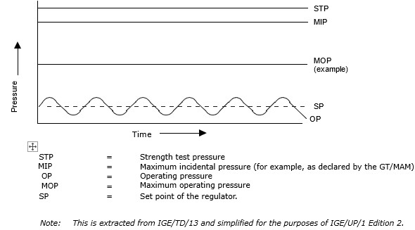
Note 4: “MOP” and other new terms such as “maximum incidental pressure” (MIP) and OP have been introduced to reflect gas pressure terminology used in European standards. Appendix 1 defines these terms and it is possible to equate them to terms used in Edition 1. These terms will arise in all relevant IGEM technical publications in future and, possibly, in other standards.
Referring to Figure 1, note how OP is shown to oscillate about the set point (SP). Note also that MOP can be declared at any value from OP upwards to a limit below MIP. The strength test pressure (STP) has to be at least 110% MIP and in many cases (see Table 1) will be greater.
For a new system of installation pipework, the onus is on the designer to establish both MIP and MOP. For an existing system of installation pipework, the onus is on the designer/owner of the system to ensure that any increase in pressure within the system will not result in OP exceeding MOP of the system and on the gas transporter (GT)/meter asset manager (MAM) to ensure that any change in their pressure regimes due to fault conditions will not jeopardise the safety of the downstream system. This involves effective communication between the GTs/MAMs and system designers/owners.
IGE/UP/1A Edition 2 deals with tightness testing and direct purging of small low pressure NG installations of volume not exceeding 1 m3 and diameter not exceeding 150 mm on industrial and commercial premises.
IGE/UP/1B deals with tightness testing and purging of domestic-sized NG installations.
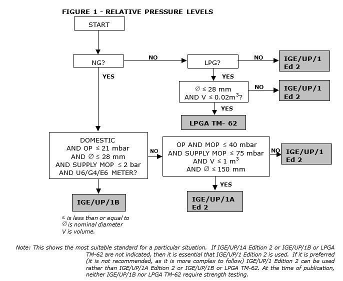
It is necessary to check the scope of referenced standards before proceeding.
FIGURE 2 - ALGORITHM TO SELECT TESTING AND PURGING STANDARDS
LPGA TM-62 deals with tightness testing of domestic-sized liquefied petroleum gas (LPG) pipework (volume not exceeding 0.02 m3). For greater volume, IGE/UP/1 Edition 2 applies.
Figure 2 will assist in selecting the appropriate standard.
1.4 It has been recognised that certain activities outlined in IGE/UP/1 Edition 2 are only required for “large” installations and/or higher pressures and/or gases other than NG. By removing some of the procedures to the Appendices, procedures for the more routine activities i.e. on smaller, lower pressure NG installations, are much simpler to identify.
In addition, the Procedures attempt to highlight the process for the majority of installations by the use of black text with blue for less common situations. Typically, black text would apply for a pipework section of MOP not exceeding 100 mbar, to operate on NG, using a water gauge or low resolution electronic gauge requiring a short test where correction for temperature and pressure is not required, and not removing any meter. However, before ignoring the remaining (blue) text, the user has to ensure that none of the test parameters fall outside those indicated by the black text. Therefore, it is important to be familiar with all the contents of the book.
Green text is used for examples illustrating individual procedures.
Note: The above does not apply to diagrams, where the colours used do not follow these principles.
1.5 There are several reasons why it was necessary to introduce a 2nd edition of IGE/UP/1, including:
- to take into account changes in technology and application since IGE/UP/1 Edition 1 was published
Note: This is particularly important with the increasing use of PE pipe, higher pressures and developments in gauge technology.
The test procedures may have to vary for PE compared to steel pipework due to the creep properties - these variations are explained in detail.
- to simplify the decision making and calculations while retaining the same standards of safety. The basic concept of ensuring a maximum safe energy release remains
- comments had been made suggesting the layout of Edition 1 could be improved. Important data needed for each calculation was in the Appendices rather than in the main body of text. The vision for Edition 2 was a document where the user progresses through the pages logically, finding the information they need for the calculations as they go, rather than having to refer to Appendices. This principle holds for the majority of installations and circumstances (see Sub-Section 1.4). In some instances, there will be a need to use the more complex guidance given in the Appendices.
1.6 These Procedures make use of the terms “should”, “shall” and “must” when prescribing particular procedures. Notwithstanding Sub-Section 1.9:
- the term “must” identifies a requirement by law in Great Britain at the time of publication
- the term “shall” prescribes a procedure which, it is intended, will be complied with in full and without deviation
- the term “should” prescribes a procedure which, it is intended, will be complied with unless, after prior consideration, deviation is considered to be acceptable.
Such terms may have different meanings when used in legislation, or Health and Safety and Executive (HSE) Approved Code of Practice (ACoPs) or guidance, and reference needs to be made to such statutory legislation or official guidance for information on legal obligations.
1.7 The primary responsibility for compliance with legal duties rests with the employer. The fact that certain employees, for example “responsible engineers”, are allowed to exercise their professional judgement does not allow employers to abrogate their primary responsibilities. Employers must:
- have done everything to ensure, so far as it is reasonably practicable, that “responsible engineers” have the skills, training, experience and personal qualities necessary for the proper exercise of professional judgement • have systems and procedures in place to ensure that the exercise of professional judgement by “responsible engineers” is subject to appropriate monitoring and review
- not require “responsible engineers” to undertake tasks which would necessitate the exercise of professional judgement that is not within their competence. There should be written procedures defining the extent to which “responsible engineers” can exercise their professional judgement. When “responsible engineers” are asked to undertake tasks which deviate from this they should refer the matter for higher review.
1.8 It is now widely accepted that the majority of accidents in industry generally are in some measure attributable to human as well as technical factors in the sense that actions by people initiated or contributed to the accidents, or people might have acted in a more appropriate manner to avert them.
It is therefore necessary to give proper consideration to the management of these human factors and the control of risk. To assist in this, it is recommended that due regard be paid to HS(G)48.
1.9 Notwithstanding Sub-Section 1.7, these Procedures do not attempt to make the use of any method or specification obligatory against the judgement of the responsible engineer. Where new and better techniques are developed and proved, they should be adopted without waiting for modification to these Procedures. Amendments to these Procedures will be issued when necessary, and their publication will be announced in the Journal of the Institution and other publications as appropriate.
1.10 Requests for interpretation of these Procedures in relation to matters within their scope, but not precisely covered by the current text, should be addressed in writing to Technical Services, The Institution of Gas Engineers and Managers (IGEM), Charnwood Wing, Ashby Road, Loughborough, Leicestershire, LE11 3GH and will be submitted to the relevant Committee for consideration and advice, but in the context that the final responsibility is that of the engineer concerned. If any advice is given by or on behalf of IGEM, this does not relieve the responsible engineer of any of his or her obligations.
1.11 These Utilization Procedures were published on 30th June 2003. They may be used rather than IGE/UP/1 Edition 1 immediately but a lead-in period is allowed, permitting the use of Edition 1 until 31st September 2003.
1.12 Italicised text is informative and does not represent formal Procedures.
1.13 Appendices are informative and do not represent formal Procedures unless specifically referenced in the main sections via the prescriptive terms “should”, “shall” or “must”.
Scope
2.1 These Procedures apply to any section of pipework including any appliance/plant pipework:
- for NG, from the outlet of the ECV (fitted on the end of the gas service that is owned by the GT)
Note: This does not include a gas service (see IGE/TD/4). - for LPG, from the outlet of the bulk storage vessel or cylinder valve (as appropriate)
Note: This does not include a gas service (see the Gas Safety (Installation and Use) Regulations (GS(I&U)R)). - for other gases (see Sub-Section 2.2) on customers’ premises, from the outlet of the isolation point from a distribution system
Note 1: This includes any primary or secondary meter installation (see Appendix 1).
Note 2: These Procedures may be applied for risers and laterals.
Note 3: The diversity of industrial and commercial gas installations is such that it is inappropriate to provide detailed guidelines for all types of installation covered by the scope of these Procedures. It is recognised that special circumstances may occur, on an installation, for which some of these Procedures cannot be applied. In such a case, for example where the volume of pipework cannot be readily calculated, whether testing or purging, a specific testing or purging procedure needs to be developed that has a comparable sensitivity and level of safety. The procedure needs to be developed by personnel of adequate competency and experience.
2.2 These Procedures cover strength testing and tightness testing, and direct purging, of pipework containing NG, Butane, Propane, LPG/Air (SNG and SMG) and Coal Gas.
Note 1: GS(I&U)R (see Section 3) define “gas” to include 1st, 2nd and 3rd family gases as well as other gases. The principles of IGE/UP/1 Edition 2 may be used for gases other than those above but suitable adjustments to stated parameters and procedures will need to be considered by a competent person.
Note 2: IGE/SR/22 deals with purging of certain other fuel gases not listed above.
Note 3: See Sub-Section 2.7 regarding the principles adopted for the detection of leakage.
2.3 These Procedures cover pipework of MOP not exceeding 16 bar.
Note: Provided suitable precautions are taken, and subject to a risk assessment, these Procedures may be used as a basis of a written procedure for testing of pipework of MOP exceeding 16 bar.
The scope does not cover installations where the upstream system MOP exceeds 75 mbar without a meter inlet valve (MIV) fitted between the regulator/PRI and any meter.
Note : The principles of IGE/UP/1 Edition 2 may readily be applied for such installations.
2.4 These Procedures apply to strength testing and/or tightness testing pipework of any diameter in the following circumstances:
- new pipework
- alteration to, replacement of, re-use of, or uprating (for example increasing OP) existing pipework
- new extensions to existing pipework
- prior to any work (see Appendix 1) on existing pipework
- where there is a known or suspected gas leak in pipework
- where there has been a complete loss of pressure for any reason
Note: The closure of a valve, for example the ECV, can result in a complete loss of pressure which necessitates tightness testing and purging before resumption of supply. - routine testing of existing pipework
- immediately before purging pipework (except when taking pipework permanently out of service).
Note: If considering strength testing of existing pipework, refer to clause 4.2.2.
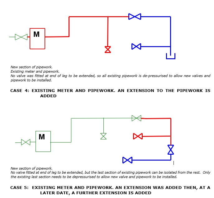
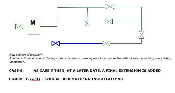
Typical schematic NG installations are shown in Figure 3 which illustrates the differences between new and existing pipework and meters and the implications for strength and/or tightness testing.
2.5 These Procedures apply to direct purging in the following circumstances:
- new pipework
- alteration to, replacement of or re-use of, existing pipework
- new extensions to existing pipework
- where there has been a complete loss of pressure for any reason
Note: The closure of a valve, for example the ECV, can result in a complete loss of pressure which necessitates tightness testing and purging before resumption of supply.
- where there is the possibility of air being present in pipework
- where pipework is to be taken out of service temporarily or permanently.
The Procedures apply when purging pipework of diameter not exceeding
150 mm of any length, and for pipework of diameter exceeding 150 mm limited to the maximum lengths given in relevant tables.
2.6 All pressures quoted are gauge pressures unless otherwise stated.
2.7 IGE/UP/1 Edition 2 adopts the concept of “gauge readable movement (GRM)”. When using a water gauge, it may be possible to reduce the duration of tests for new installations and extensions by adopting the concept of “no perceptible movement”. This will lower test times in many cases but has to be subject to a thorough analysis, by the responsible person, of the complex fluid mechanics and mathematics involved.
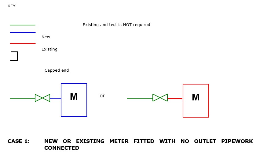
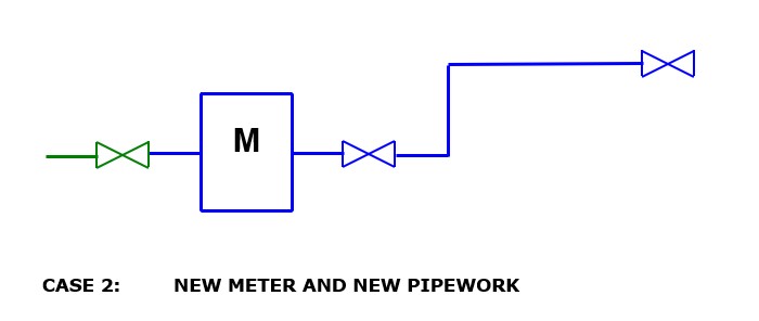

FIGURE 3 - TYPICAL SCHEMATIC NG INSTALLATIONS